Overview

Early Accelerated Wear Tester Prototype
(details blurred to retain confidentiality)
High-speed video is an integral part of prosthetic heart valve durability testing, especially given the updates in ISO 5840-1:2021 that place greater emphasis on leaflet kinematics. As such, one of my responsibilities while on co-op at Vivitro Labs was to design and specify a high-speed camera system for a new Accelerated Wear Tester (AWT) that could be efficiently transferred between testing units with consistent valve framing and image quality. By the end of my co-op term, I had specified a lens for aortic valves, designed and tested multiple camera mounting and lighting prototypes, and refined camera and light mounting designs. Although done in parallel, this project can be broken into two main components:
- Camera System - encompasses the specification of a lens and the design of mounting for an AOS PROMON U1000 high-speed video camera. (Full report on camera mounting here)
- Lighting System - includes the specification and layout of LEDs, collaboration on a PCB, and the design of mounting.
Background
Medical devices can be vital to treating patients with cardiovascular disease; any failure can have life-altering consequences. Vivitro Labs is a company dedicated to reducing the risk to patients by developing cardiovascular device testing equipment, offering laboratory testing, and providing consulting services. While working at Vivitro as a Mechanical Engineering Co-op, my time was primarily spent contributing to the development of a new prosthetic heart valve durability tester.
Prosthetic Heart Valve Durability Testing
Although Vivitro currently sells an AWT, the HiCycle, design limitations and advances in the market have led them to begin developing a new AWT with cycling speeds 300-2100 BPM, or 5-35 Hz. While capable of higher speeds, cycle frequency is often limited by the valve; at least 95% of the cycles must have defined pressure differentials consistent with normotensive conditions for at least 5% of the cycle’s duration, and leaflet kinematics must be consistent with those observed in the hydrodynamic assessment.

General Heart Valve Durability Testing Procedure
Hydrodynamic Assessment is done with more physiologically accurate speeds and conditions using equipment like Vivitro's Pulse Duplicator.
The Problem

Preliminary Accelerated Wear Tester Model
The base configuration of the AWT comprises of six physical testing units, one high-speed camera, a controller, and a data acquisition box. This base configuration can also be customized to include more controllers and testing units as requested.
Objectives
Camera System
- Take less than one minute to remove and install between units
- Consistently locate the camera relative to the valve
- Cost less than 500 USD for small production runs of around 10 units (excluding camera and camera lens)
- Capture the full width and depth of any aortic or mitral valve with one lens
Light System
- Sufficient light to illuminate a prosthetic heart valve when recording video at 817-1000 FPS
- Take less than 30 seconds to remove from a unit
- Illuminate the valve evenly with minimal shadows
Additional Considerations
- One of the primary design objectives of the new AWT is to provide exceptional valve visibility
- Corrosive saline solution spills are common and expected throughout durability testing
- Most users will be working with latex gloves on in a small laboratory setting
The Designs
After defining the design objectives and constraints, I created concept models using Solidworks while specifying a suitable lens for aortic valves. Since Vivitro also runs a testing lab, I was able to gain valuable feedback and insight from end users throughout the design process.
Camera System
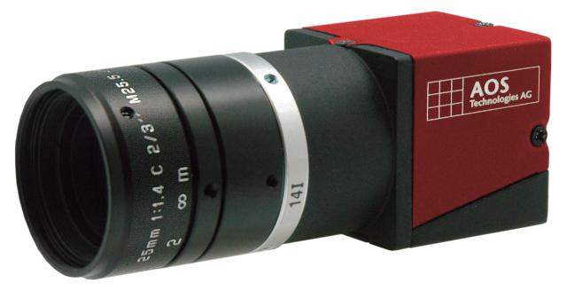
AOS PROMON U1000
Before I joined Vivitro, the PROMON U1000 high-speed camera was specified for the new AWT.
Camera Lens
- Object Distance
- Camera Resolution
Click here for documentation on the aortic lens specification process.

VS-LDA20
The VS-LDA20 was chosen as the specified aortic valve lens. While remaining relatively inexpensive, this 20 mm focal length lens provided enough adjustability to capture the full width and depth of field for all aortic valves when used in combination with the camera mount's vertical adjustability
Camera Mounting
While specifying lenses, I generated several design concepts with SolidWorks and reviewed them with the R&D and lab testing teams. A number of these concepts can be seen below, including one with three variations:

Concept 1 - Pillow Block
An aluminum rod is clamped by two pillow blocks that are mounted to the AWT's lower valve chamber. This concept was developed so that the camera could also be mounted below the valve, an objective was removed after a discussion with lab staff revealed how infrequently this was needed.

Concept 2A - Top Mounted (18mm)
This concept features base plate connector clamps mounted to each testing unit and an 18 mm rod that slots into each unit's back chamber. The intent behind this approach was for users to simply undo the base clamp and move the rod and camera together.

Concept 2B -Top Mounted (20mm)
A combination of concern for mounting rigidity when exposed to the AWT's vibrations, and the existence of a camera mounting bracket at Vivitro compatible with 20 mm rods led me to design a variation of 2A with this base connector clamp and a 20 mm rod.

Concept 2C - Back Mounted (18mm)
This version of Concept 2 opts for a flanged connector clamp mounted to the rear of the back chamber, but is functionally similar to concepts 2A and 2B. This design was created to offer an option that could be used with Vivitro's Pulse Duplicatorwith minor modifications.

Concept 3 - Automated Stage
By employing an automated stage, this option presents an ideal user experience. However, this concept was likely prohibitively expensive and difficult to execute in a way that allows the same level of modularity that the new AWT architecture will offer.
After several design reviews and concept iterations, it was decided that each variation of Concept 2 would be refined and made into prototypes for testing. Additionally, feedback from a Test Engineer on vertical camera adjustment led me to introduce a Novoflex focusing rack as the primary method of adjusting the camera’s height. Lastly, I found the approximate natural frequency of the camera system, camera and Novoflex included, using hand calculations and a Solidworks simulation.

Novoflex CASTEL-MINI II Focusing Rack
This manual focusing rack allows for easy and consistent camera height alteration that cover the full range of adjustment needed for most aortic valve sizes with the lens specified above.

Refined Concept 2A Model
As can be seen, the Novoflex focusing rack was integrated and a bracket that clamps onto the rod was designed.

Concept 2A SolidWorks Simulation
The undamped natural frequency of the camera system was calculated to be ~117 Hz, while the SolidWorks simulation resulted in ~119 Hz (camera and Novoflex mass lumped into the bracket's weight).
Lighting System

Cree XLamp XM-L2 LED
This LED was choosen for its high luminosity and thermal efficiency.
Light Mounting
Working together on form factor, the other co-op student designed the PCB while I primarily focused on its mounting. Much like with camera mounting, a number of concepts were generated and reviewed.

Concept 1 - Simple Ring
Attaching to a bracket for modularity, this concept was kept relatively simple to allow for the majority of machining to take place in one operation on a lathe. This concept was made out of aluminum and was inteded to act as a heat sink for the PCB.

Concept 2 - Camera System Mounted
Clamping onto the camera mounting rod, this concept was designed to be vacuum cast out of acetyl and moved between testing units with the high-speed camera.

Concept 3 - Valve Chamber Mounted
Resting on the top of the angled valve chamber, this concept was designed to be vacuum cast out of acytal much like Concept 2. However, this design was made with the intent of outfitting a light to each testing unit.
While concept 1 was designed to be made using conventional machining methods, concepts 2 and 3 were originally designed for 3D printing. However, once it was decided that concepts 2 and 3 would be made for testing, the designs were modified to be compatible with conventional machining methods and vacuum casting at production scale.
Heat Management

Light Ring PCB Model
This PCB was made with 6 and 12 LED variations.
The Results
Prototypes of each camera mounting concept, along with each light mounting, were successfully manufactured and assembled.

AWT Prototype with Light Mount Concept 2
Camera Mounting: Concept 2A
Light Mounting: Concept 2

Light Mounting Prototypes
Concept 2 (left) and Concept 3 (Right)

AWT with Light Mount Concept 3
Camera Mounting: Concept 2A
Light Mounting: Concept 3
Field Width and Depth of Field
To confirm that the camera lens, focusing rack, and lighting were collectively capable of capturing the full range of aortic valve sizes, a test marker was designed and 3D printed with the largest and smallest expected diameters and depths of prosthetic aortic valves. As can be seen by the frames taken from a high-speed video recording below, the camera mounting system provides sufficient adjustability to capture the full range of aortic valves.

Field Width and Depth of Field Test Results
The AOS focusing tool overlay highlights details deemed to be in-focus. As can be seen, both the high points (the edges of each ring), and the base are within focus, confirming that there's sufficient depth of field.
Since prosthetic mitral valve dimensions tend to vary less than those of aortic valves, it was determined that the camera mounting system provided sufficient adjustability to also accommodate most mitral valves, given a properly specified lens.
Camera Transfer Speed and Frame Repeatability
Testing of the camera mounting system’s transfer speed and frame repeatability was done in parallel.
- It was found that it took an average of 42 seconds over five tests to remove and re-install the camera.
- It was also found that the camera mounting system reliably located the camera relative to the test valve, as shown below.

Frame Location Repeatability Test Results
The red marker remained on the same pixels for all repeatability testing. Since there is only one prototype unit, the potential for tolerance stack-up between components could not be tested, however, the maximum offset due to this was calculated to be 1 mm, or 0.05% of a small aortic valve’s diameter. Therefore, it was determined that tolerance stack-up is not a large concern, especially relative to the tolerances on the valve holders.
Image Stability
To test the stiffness/stability of the camera mounting system, the AWT was set to frequencies between 10 and 35 Hz in 5 Hz steps. Since the AWT’s natural frequency was found to be 22Hz, this frequency was also tested. Given time constraints, I was unable to quantify the amplitude of vibrations captured in high-speed video. Therefore, qualitative notes were taken and summarized below. All configurations failed to provide adequate stability throughout the expected operational range.
| Excitation Frequency (Hz) | Standard 18 mm Configuration | 18mm Rod with Pulse Duplicator Bracket | 20 mm Rod with Pulse Duplicator Bracket |
|---|---|---|---|
| 10 | Stable | Stable | Stable |
| 15 | Fairly stable | Fairly stable | Fairly stable |
| 20 | Somewhat stable | Somewhat stable | Somewhat stable |
| 22 | Small vibration noticeable | Small vibration noticeable | Somewhat stable |
| 25 | Vibration noticeable | Vibration noticeable | Small vibration noticeable |
| 30 | Significant vibration noticeable | Significant vibration noticeable | Vibration Visible |
| 35 | Significant vibration noticeable | Significant vibration noticeable | Significant vibration noticeable |
Cost
When ordering prototype parts, quotes for a low-production run of 10 AWT’s with the base configuration of six testing units were acquired. While the final cost is well below the goal of $500, it’s worth noting that the camera mounting adapter and rod designs will be simplified for the final product, further reducing costs.
| Part | Cost (USD) |
|---|---|
| Novoflex CASTEL-Mini II Focusing Rack | $ 200.00 |
| GN 162-B18-2-BL - Flanged Bracket | $ 17.56 |
| AWT – High Speed Camera Mounting Plate | $ 35.35 |
| AWT – High Speed Camera Mount Adapter | $ 75.09 |
| AWT – Camera Mounting Rod – 18mm | $ 64.62 |
| Total | $ 392.61 |
Lighting
Testing was then done to ensure the light ring could provide sufficient light to properly illuminate a dark test valve at 1000 FPS and f-stop 16. Additionally, temperatures were monitored to ensure the PCB remains sufficiently cool while operating with its maximum light output.

Bovine Tissue Aortic Valve - 12 LED Ring
Both 6 and 12 LED light rings provided sufficient light (with no shadows) to view prosthetic valve details with the least favorable camera setup for light.

IR Camera Readings
Peak temperatures were monitored using a FLIR IR camera. Notice that while the PCB backing is quite hot, the mounting remains cool enough to comfortably handle.

After 30 minutes of operation in a room ~22.8 °C, temperatures appeared to stabilize around 109 °C.

After the light was turned off, the PCB's temperature rapidly declined, reaching ambient temperature in around 15 minutes.
As can be seen above, while PCB temperatures remained low enough to avoid damaging the acetyl mounts, they still rose fairly high. However, the light output tested is rarely required for even high-speed video capture, thus it is unlikely that the peak temperatures seen will even be approached in normal operation. Nonetheless, it was advised that a timer be programmed to turn off the lights when operating at high output for over 10-15 minutes to reduce the risk of a fire or AWT damage.
Conclusion and Recommendations
Following the testing of the camera and lighting systems, along with the first AWT prototype, I worked with another engineer to introduce several modifications to the design of all three. The major changes to the camera and light mounting are summarized below:
- Updates to the design of the AWT significantly reduced the required
camera mounting rod length, improving image stability.
- This also meant that the same camera mounting prototype could be used to test camera stability.
- The 18 mm rod variant of Concept 2 was chosen and its mounting location on the AWT was centered.
- It was decided that each AWT testing unit will come with a dedicated
light, so the Concept 3 (chamber mounted) design was refined.
- Updates to the AWT’s valve chamber allowed the light ring mount to be simplified to a ring with three locating nubs and a flat.
- Black acetyl was chosen in response to the amount of light that bled through the white acetyl prototypes.

Refined Camera Mounting Prototype Model
Some vertical adjustability beyond the Novoflex focusing rack left to allow for easy handling and modularity.

Refined Light Mount Prototype Model
It was decided that each testing unit should get a light, thus the chamber mounted concept (Concept 3) was refined and modified to interface with the updated AWT valve chamber.

Refined Light Mount Prototype
The refined light mount was made after I left Vivitro. However, I was told it worked well.
Within the last week of my co-op, we successfully submitted drawings to a manufacturer to be made over the holiday break. Additionally, before leaving, I calculated and suggested a target spring rate for vibration isolating feet to reduce the amplitude of vibrations observed by the AWT when in operation, especially at 22 Hz.